")
")
")
")

")
")

Multiparva 3.0 F 115
-

MODULATION 1:8
-

MAX PRESSURE 6 BAR
-

NATURAL GAS / LPG
-

PERFORMANCE 97,4%
-

ENERGY RATING


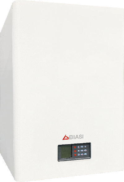
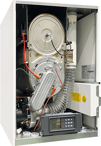
Multiparva 3.0 is a latest generation extremely high efficiency condensing boiler for heating only, equipped with a pre-mixed modulating burner with low emissions and stainless steel condensing heat exchanger with high calorific power values. It is available from 35, 45, 70, 95, 110, 115, 150 heat capacity . It can be installed individually or up to 6 modules can be combined, of the same or mixed heat outputs, directly exploiting the boiler electronic control unit. Multiparva Cond 3.0 exploits the condensing principle: thanks to the innovative heat exchanger in stainless steel and the two separate sections, one dedicated to condensing only, it is able to recover the latent heat contained in the flue gases, obtaining efficiency levels which are some of the highest in the category. Multiparva Cond H can be installed inside a boiler room or, thanks to the Roof Top version, it can be enclosed inside a cabinet on the outside of the building or on the roof itself. This solution is extremely advantageous in the case of thermal requalification of a boiler plant.
The Multiparva 3.0 condensing boiler can be installed individually in heating only (SR) or heating installations with provision for combination with a remote boiler (SV), thanks to the combination of the appropriate kits.
It can be installed inside a boiler room or, thanks to the specific Roof Top version enclosed inside a cabinet, outside the building or on the roof of the same, an extremely advantageous solution in case of redevelopment of a thermal power plant. The module is pre-assembled and contains the boiler and its kit (SR or SV) inside.
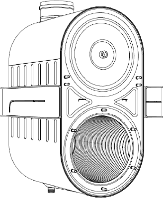
New DUOPOWER exchanger
For power from 115 kW duopower model 12+6
FEATURES
- Composed by two overlapping chambers
- Entirely in stainless steel
- Maximum working pressure 6bar
- Maximum pressure drops between 4.2 and 4.5 mca
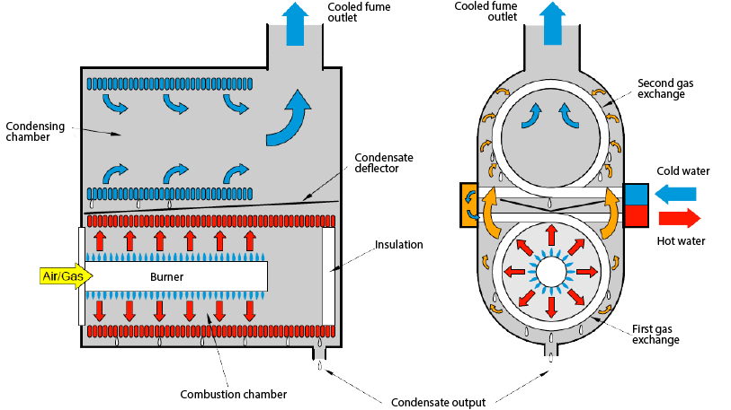
Operation diagram
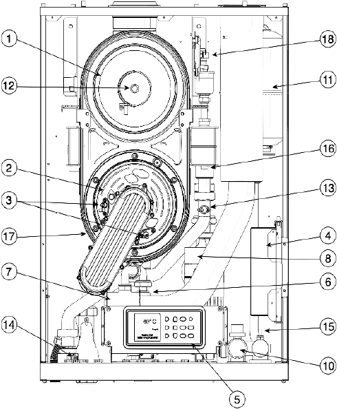
- 1. Exchanger
- 2. Burner
- 3. Electrodes
- 4. Electronic board
- 5. Display
- 6. Gas valve
- 7. Fan
- 8. Circulator
- 9. Pressure transmitter
- 10. Safety valve (5.4 bar)
- 11. Expansion vessel
- 12. Flue gas probe
- 13. Safety thermostat
- 14. Discharge probe
- 15. Return probe
- 16. Body probe
- 17. Thermal fuse
- 18. Siphon pressure switch (all models) Pressure switch APS (M158HE.115/F & M158HE.150/F)
Principle scheme
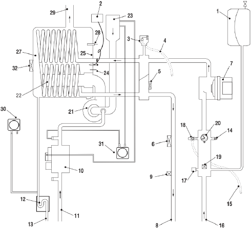
- 1. Expansion vessel (model F only)
- 2. Remote igniter
- 3. Automatic vent valve
- 4. Vent discharge
- 5. Boiler body NTC probe
- 6. Safety thermostat
- 7. Modulating circulator (only model F)
- 8. Heating flow pipe
- 9. Heating flow NTC probe
- 10. Gas valve
- 11. Gas inlet
- 12. Condensate drain trap
- 13. Condensate drain pipe
- 14. Boiler drain tap
- 15. Safety valve drain
- 16. Heating return pipe
- 17. Pressure transducer
- 18. Safety valve not qualified (only modelF)
- 19. NTC probe heating return
- 20. Pressure gauge
- 21. Fan
- 22. Burner
- 23. Air intake duct complete with silencer
- 24. Flame detection electrode
- 25. Combustion chamber thermostat
- 26. Ignition electrode
- 27. Condensing primary exchanger
- 28. Flue gas probe
- 29. Flue gas expulsion duct connection
- 30. Siphon pressure switch
- 31. Air pressure switch (APS) (only M158HE.115/F & M158HE.150/F)
- 32. Rear thermal-fuse
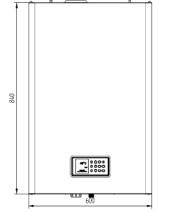
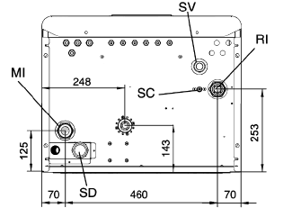
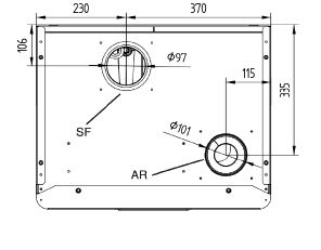
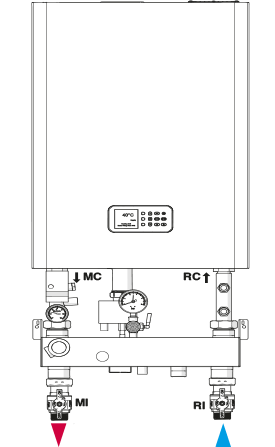
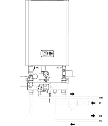
Dimensions and connections
- MI Heating delivery (1”1/4 M)
- RI Heating return (1”1/4 M)
- SD Condensate siphon drain (Ø 25 mm)
- SV Safety valve exhaust
- SC Boiler drain
Heating only configurations (SR)
The SV application kit is made by a hydraulic separator, useful for interfacing the boiler with the system, and an INAIL safety unit compliant with the “R” collection. Safety unit complying with the requirements of the “R” collection. It is also available in the version for free installation with heat exchanger and INAIL safety group, as an alternative to the SR application kit.
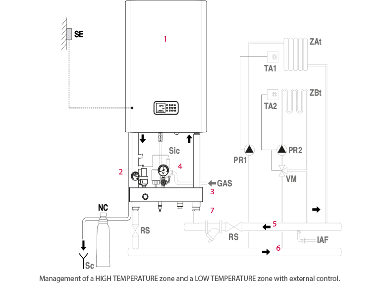
- 1. Boiler
- 2. INAIL safety module
- 3. Hydraulic separator (*)
- 4. Fuel shut-off valve
- 5. System return collector
- 6. System delivery collector
- 7. Purification filter
- SE External probe (*)
- NC Condensate neutraliser (*)
- Sc Discharge
- RS System breaker cock
- ZAt High temperature zone
- ZBt Low temperature zone
- TA1 High temperature zone ambient thermostat
- TA2 Low temperature zone ambient thermostat
- PR1 High temperature system pump
- PR2 Low temperature system pump
- VM Low temperature system mixer valve
- Sic Fuel shut-off probe
- GAS Fuel supply
- IAF Cold water inlet
Heating configurations + DHW (SV)
The SV application kit consists of a hydraulic separator, which is useful for interfacing the boiler with the system, and a unit INAIL safety iaccording to the requirements of the “R” collection, it is also equipped with a circulator for loading a possible boiler.
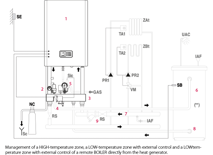
- 1. Boiler
- 2. INAIL safety module
- 3. Hydraulic separator (*)
- 4. Water heater coil pump (*)
- 5. Fuel shut-off valve
- 6. Remote water heater (**) (managed directly from the boiler via a 3-way valve)
- 7. System return collector
- 8. System delivery collector
- 9. Purification filter
- SE External probe (*)
- NC Condensate neutraliser (*)
- SB Water heater probe (*)
- Sc Discharge
- RS System breaker cock
- ZAt High temperature zone
- ZBt Low temperature zone
- TA1 High temperature zone ambient thermostat
- TA2 Low temperature zone ambient thermostat
- PR1 High temperature system pump
- PR2 Low temperature system pump
- VM Low temperature system mixer valve
- Sic Fuel shut-off probe
- GAS Fuel supply
- IAF Cold water inlet
- UAC Hot water outlet
(*) Available as an accessory. (**) In this configuration the use of a water heater with a coil of a suitable size is recommended.
MMI remote control
Simple MMI is a remote user interface (or ambient unit) equip- ped with an OpenThem® communication protocol which is designed to control the boiler (remote control) and the zones in which it is installed (chronothermostat with weekly set- tings). Thanks to two-way communication with the boiler, the Simple MMI module lets the user check/set the temperature of the heating water and the DHW without having to go to the boiler plant.
Functional features
The Simple MMI is a remote control for boilers with a weekly time program.
The main features are:
- Weekly programming clock
- Automatic or manual operating mode
- Activation/deactivation of DHW and heating (radiators)
- Display of ambient temperature and time
- “Smart Shower” function which allows the temperature of the DHW to Display of be set at the required level for a set time
- Display of boiler settings
- Two-way communication with the boiler via the OpenTherm® protocol
Display of system information
Each time the knob K4 is pressed, the following system information is displayed in a cycle:
- Temperature outside the building (simple display, only if connected to the relative sensor)
- Temperature set for the water in the heating system (turn the knob K4 to modify the set value)
- Temperature set for the hot water in the DHW system (turn the knob K4 to modify the set value). This is the default temperature when the “Smart Shower” function is not active
- Actual temperature of the water in the heating system (simple display)
- Actual temperature of the hot water in the DHW system (simple display)
- Ambient temperature (simple display)

Plant standard schemes
Schematic diagram of centralised system with single boiler, heating with metering, DHW produced by boiler + solar thermal.
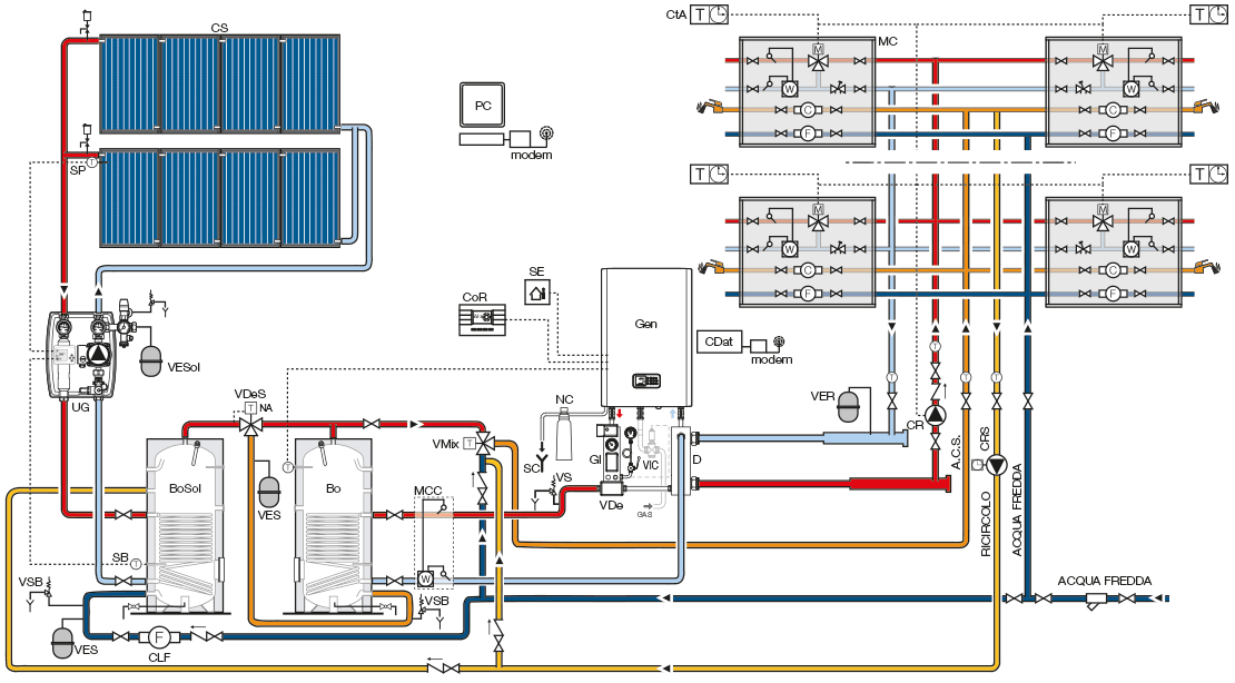
- Bo Single-coil water heater
- BoSol Single-coil solar water heater
- CDat Data concentrator
- CLF Cold water meter (litres)
- CoR Remote control
- CR Heating system pump
- CRS DHW recirculation system pump
- CS Solar collector
- CtA Ambient chrono-thermostat
- D Separator
- GI INAIL safety unit
- Gen Gas combination heat generator
- MC Module for metering heating, DHW and Cold Water
- MCC Central plant heat meter
- NC Acidic water passivator
- SB Water heater probe
- SC Condensate drain
- SE External probe
- SP Panel probe
- UG Electronic control unit and hydraulic unit
- VDe 3-way diverter valve
- VDeS 3-way DHW diverter valve
- VER Heating expansion vessel
- VES DHW expansion vessel
- VESol Solar expansion vessel
- VIC Fuel shut-off valve
- VMix DHW mixing valve
- VS Safety valve
- VSB Water heater safety valve